
What Are CNC Lathe Parts and How Do They Work?
CNC lathes turn rotating stock into precise components, from threaded shafts to smooth bushings. Their results depend on more than the cutting tool. The spindle, chuck, turret, tool holders, and control system must work together. Each component has a clear job. Small details matter.
The global CNC machine market was valued at USD 83.99 billion in 2023, according to Fortune Business Insights’ industry report. That estimate covers a broad market, not lathe parts alone, but it signals the scale of computer-controlled machining. CNC educator Mike Lynch, founder of CNC Concepts, emphasizes a related practical lesson in his published guidance: reliable machining depends on sound setup and verification, not code alone. This is a paraphrase, not a direct quotation.
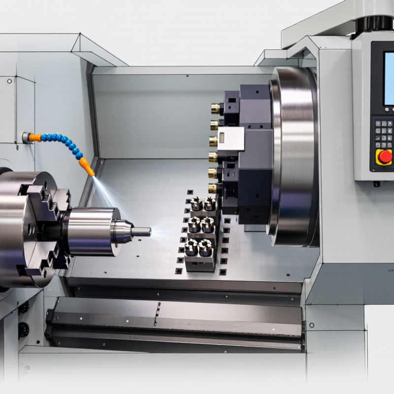
Inside a CNC lathe, the chuck grips the workpiece while the spindle rotates it. A programmed turret positions cutting tools against the material. The control coordinates movement, speed, and feed, shaping the part in measured passes. Coolant can reduce heat and carry chips away. Yet even a well-written program cannot compensate for a loose workpiece or worn insert. That is easy to overlook. A finished surface may look correct while a bore is slightly off-size. Understanding Cnc Lathe Parts helps readers connect each machine component to accuracy, safety, and repeatable production—and recognize where inspection still matters.
What Defines a CNC Lathe and Its Main Components?
A CNC lathe is a machine tool that turns a workpiece while cutting tools shape its surface. The spindle and chuck hold and rotate the material; the bed supports the machine, while the carriage moves tools along programmed axes. A turret carries several cutting tools, allowing the machine to switch operations with little manual handling. The controller reads programmed instructions and coordinates these movements. Sensors report position, helping the system correct motion. Small errors still matter.
During a typical cycle, the chuck spins a metal bar, and a tool advances to turn its diameter or cut a shoulder. Coolant can reduce heat and carry away chips, while an enclosure helps contain them. The International Federation of Robotics’ World Robotics 2024 report counted about 4.28 million industrial robots operating worldwide in 2023. That figure reflects factory automation broadly, not CNC lathes alone. It offers context, not proof that every lathe uses robotic loading. In practice, setup, tool wear, and workpiece clamping can affect accuracy, even when the program appears correct.
What Are CNC Lathe Parts and How Do They Work? — What Defines a CNC Lathe and Its Main Components?
| Component | What It Does | How It Works | Role in Turning |
|---|---|---|---|
| CNC control unit | Reads the part program and coordinates machine movements and operating functions. | Interprets programmed commands, such as tool paths, spindle speed, feed rate, and auxiliary functions, then sends instructions to the machine’s drive and control systems. | Provides the automated, repeatable control that distinguishes a CNC lathe from a manually operated lathe. |
| Machine bed and guideways | Support the main machine assemblies and provide defined paths for moving components. | The bed forms the machine’s rigid base. Guideways or linear guides constrain the carriage and other moving assemblies to travel along their intended axes. | Help maintain alignment and resist cutting forces during machining. |
| Spindle | Rotates the workpiece at a commanded speed. | A motor and drive system turn the spindle. The control unit can regulate spindle speed and, on suitable machines, spindle orientation. | Supplies the rotary motion needed for operations such as facing, turning, and threading. |
| Chuck or workholding device | Holds the workpiece securely on the spindle. | Chuck jaws or another workholding arrangement grip the stock. The setup must suit the part’s shape, size, and machining forces. | Keeps the workpiece centered and stable while it rotates and is cut. |
| Turret and tool stations | Carry cutting tools and present the selected tool to the work area. | On a turret-style lathe, the turret indexes to bring a programmed tool station into position. Toolholders secure inserts, drills, or other compatible tools. | Allow different machining operations to be performed in sequence, often without manually changing tools. |
| Tooling and cutting insert | Remove material from the workpiece to create the required geometry. | The cutting edge engages the rotating workpiece as the tool advances. Tool shape, material, and cutting conditions are selected for the operation and workpiece material. | Creates features such as diameters, shoulders, grooves, and threaded surfaces. |
| Axis drive system | Moves the turret, carriage, or other controlled assemblies along programmed axes. | Servo motors and mechanical transmission elements, such as ball screws or direct-drive systems, convert control commands into precise motion. Many CNC lathes use X and Z axes; some include additional axes. | Controls tool position and feed relative to the rotating workpiece. |
| Tailstock or sub-spindle | Provides support or additional workholding, depending on the machine configuration. | A tailstock can support the free end of a long workpiece with a center or hold axial tools. A sub-spindle can grip and transfer a part for machining from another side. | Helps machine long or slender parts, or supports additional operations on suitable machines. |
| Coolant and chip-management system | Delivers cutting fluid where required and manages chips produced during machining. | A pump may circulate coolant through nozzles or tooling passages. Chip conveyors or other collection systems move chips away from the cutting area. | Can help control heat, lubricate the cutting zone, and keep chips from interfering with machining. |
| Enclosure and safety interlocks | Separate the operator from the machining area and help contain chips and coolant. | Guard doors enclose the work zone. Interlocks can prevent or stop certain machine functions when a guard is open, according to the machine’s safety design. | Support safer operation; guards should remain in place during automatic machining. |
| What defines a CNC lathe? | A lathe in which a computer numerical control system directs programmed machining movements. | The workpiece is commonly rotated by the spindle while one or more tools move along controlled axes to remove material. Configurations and capabilities vary by machine. | Typical work includes producing cylindrical features, but the exact operations depend on the machine, tooling, and setup. |