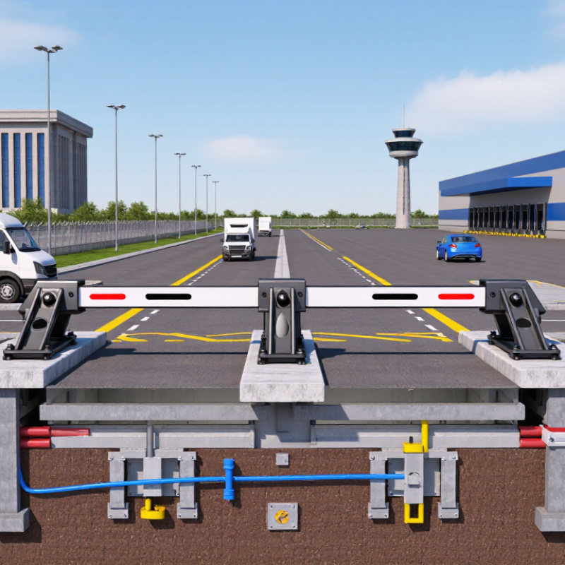
Choosing a Vehicle Wedge Barrier for international projects requires more than comparing prices or steel thickness. Buyers must connect threat assessment, site conditions, certification, and daily traffic needs. A barrier protecting a government entrance may face different risks from one serving a logistics warehouse or airport service road. The right choice begins with evidence, not attractive brochures.
Industry research supports this careful approach. Grand View Research’s 2024 Physical Security Market Size, Share & Trends Analysis Report identifies perimeter protection as a continuing investment area for commercial and critical facilities. However, market growth does not prove that every product performs equally. ASTM F2656/F2656M and IWA 14-1 provide recognised methods for evaluating vehicle impact resistance. Their ratings should be checked against vehicle mass, approach speed, penetration distance, and test configuration. A rated barrier is not automatically a suitable barrier.
Global buyers should also examine the installation reality. A wedge unit may need reinforced concrete, reliable drainage, underground space, and controlled access integration. Ask for full test reports, maintenance intervals, hydraulic cycle data, emergency operating procedures, and local service capability. Watch the entrance during peak traffic. A barrier that opens slowly can create queues, unsafe reversing, and frustrated operators. Some specifications look impressive but ignore climate, soil movement, salt exposure, or power failure. That is a common weakness.
This guide will compare key technical and procurement factors. It will help buyers assess the Vehicle Wedge Barrier as a complete security system, rather than an isolated piece of steel. Requirements still vary by site. Professional review remains essential.
How to Choose a Vehicle Wedge Barrier for Global Buyers?
Vehicle wedge barriers combine a rising steel plate, hydraulic drive, hinges, and reinforced foundations. Their purpose is simple: stop hostile vehicle intrusion before it reaches people or buildings. The structure matters more than appearance. A shallow wedge may suit controlled entrances, while a deep wedge usually provides stronger resistance. ASTM F2656-20 tests barriers with a 15,000-pound vehicle at defined impact speeds. IWA 14-1 also measures vehicle mass, speed, and penetration distance. These ratings offer useful evidence, not absolute promises.
Protection levels should match the site risk. M30, M40, or M50 ratings indicate tested impact speeds under ASTM methods. The penetration result shows how far the vehicle travels after impact. A higher rating is not automatically wiser. It may require deeper excavation, stronger drainage, slower operation, and higher maintenance costs. Grand View Research valued the global physical security market at about USD 127.01 billion in 2023. This growth reflects wider demand, but market growth does not replace site-specific engineering. In practice, poor foundation design can weaken an excellent barrier. That is an uncomfortable detail.
Tips: Ask for the complete crash-test certificate, not only a rating label. Check vehicle weight, speed, penetration, foundation details, and test direction. Review hydraulic cycle time and manual release procedures. Leave room for mistakes. Operators may misread signals, and water may enter the pit. Independent structural review and local soil assessment can prevent expensive surprises.
Vehicle wedge barriers are selected according to the required impact-test rating, site risk, vehicle access requirements, and installation conditions.
The chart shows the test speeds associated with ASTM F2656 M30, M40, and M50 ratings: 30, 40, and 50 mph respectively. These ratings are based on standardized vehicle-impact testing and should not be interpreted as a guarantee for every vehicle, installation, or site condition. Buyers should verify the complete certification, penetration rating, foundation design, drainage requirements, cycle frequency, and emergency-access configuration before selecting a barrier.
Choosing a vehicle wedge barrier starts with the site, not the catalog. Map every approach lane, gate, pedestrian route, and emergency access point. Measure road width, turning radius, pavement depth, drainage, and available foundation space. A barrier may stop a heavy vehicle yet fail when poor drainage weakens its pit. Look for blind corners, downhill approaches, queues, and loading areas. These details reveal the practical threat.
Define vehicle risks by mass, speed, approach angle, and likely impact location. A slow service truck needs a different design from a fast, heavy vehicle. Request independent crash-test evidence matching the required vehicle class and impact speed. Check how the system performs after impact, not only during it. Review cycle testing, hydraulic or electromechanical protection, manual release, and safe power-loss operation. Local engineers should confirm soil conditions and structural loads. Generic ratings can mislead.
Global purchasing adds weather, maintenance, and compliance concerns. Salt air, dust, freezing temperatures, and intense heat can change service intervals. Ask for clear drawings, test reports, spare-part plans, and trained installation support. Confirm visibility, warning signals, and coordination with emergency procedures. In practice, buyers sometimes focus too heavily on stopping power. I have seen site layouts overlooked. That mistake creates delays and unsafe vehicle movements. Recheck assumptions before choosing a model. A modest barrier, correctly installed, may protect better than a larger one fitted poorly.
Choosing a vehicle wedge barrier starts with the site, not the product brochure. Manual systems suit low-traffic entrances with trained operators and limited power access. They are simple, visible, and often easier to maintain. However, raising a heavy wedge by hand can slow vehicle movement during busy periods. Hydraulic barriers deliver stronger lifting performance and smoother control. They work well at commercial entrances, logistics facilities, and sites requiring frequent operation. Their pumps, seals, and fluid lines need regular inspection. Automatic systems offer sensors, remote controls, and fast response times. They improve convenience, but they also depend on reliable power, control equipment, and careful installation. No option is perfect.
Tips: Check traffic volume, road width, drainage, foundation depth, and emergency access before choosing. Ask for tested impact data, duty-cycle information, maintenance intervals, and spare-part availability. Confirm that the system matches local engineering and safety requirements. A small site survey can prevent expensive changes later. I would also test the barrier during rain, darkness, and power interruption. These conditions reveal weaknesses that showroom demonstrations often hide.
Manual operation may seem economical, yet labor costs can grow over time. Hydraulic equipment may appear complex, but trained technicians can service it predictably. Automatic systems reduce daily effort, although poor sensor placement may cause delays or false triggers. Global buyers should compare total ownership costs, not only purchase prices. The cheapest design can become the most demanding one.
Choosing a vehicle wedge barrier starts with the site, not the catalogue. A 2024 NPSA hostile vehicle mitigation guide stresses risk assessment, stand-off distance, and controlled access. Measure road width, turning radius, drainage, soil strength, utilities, and emergency routes. Small errors matter. A wedge designed for 7.5-tonne vehicles may not suit a 12-tonne delivery truck. Check tested vehicle mass, impact speed, and penetration rating under ASTM F2656/F2656M-23 or IWA 14-1. These frameworks differ, so compare like with like. Do not treat a PAS 68 certificate as automatically equivalent. Request the full test report, not only a rating.
Installation planning should include concrete depth, reinforcement, power supply, controls, traffic lights, and safe failure positions. The 2023 Global Status Report for Buildings and Construction reports that buildings and construction consume about 32% of global energy. That figure is not a barrier statistic, but it supports efficient hydraulic systems and low-energy standby modes. The WHO Global Status Report on Road Safety 2023 records approximately 1.19 million annual road deaths, reinforcing the need for pedestrian separation and clear emergency exits. CISA guidance recommends layered protection and routine inspection. A barrier is only one layer. Build schedules around cycle counts, hydraulic leaks, sensors, emergency release, corrosion, and drain blockage. Keep spare seals locally when possible. ISO 22343-1 testing informs impact performance, but cannot predict every site condition. I would not trust a neat specification alone. Reality is messier.
For global buyers, choosing a vehicle wedge barrier starts with the supplier, not the product brochure. Ask for verified test reports, installation records, and clear performance data. A reliable supplier should explain stopping force, cycle capacity, drainage needs, and emergency operation in plain language. Vague answers deserve careful attention.
International deployment adds practical challenges. Check whether the barrier supports your local power supply and control systems. Confirm the supplier can provide drawings, foundation guidance, spare parts, and multilingual manuals. Request references from sites with similar traffic, weather, and operating hours. A coastal entrance may need stronger corrosion protection, while a cold region may require special hydraulic or electrical safeguards. Small details matter.
Look closely at after-sales support. Who answers during a weekend failure? How quickly can replacement parts arrive? Does the supplier train local technicians, or only send installation instructions? A useful contract should define inspection schedules, response times, documentation, and warranty responsibilities. Independent testing is valuable, but it cannot replace a site assessment. A perfect checklist does not exist. One overlooked drainage channel can delay commissioning for weeks. Supplier transparency, documented experience, and realistic technical advice usually reveal more than polished marketing language.
| Evaluation Dimension | Recommended Comparison Data | Practical Selection Guidance | Supplier Evidence to Request |
|---|---|---|---|
| Security Performance | Independent vehicle-impact test classification under ASTM F2656/F2656M, IWA 14-1, or PAS 68; test vehicle mass and impact speed must be stated. | Select a rating based on the site threat assessment. Do not compare test ratings unless the vehicle mass, speed, penetration distance, and test configuration are equivalent. | Complete test report, certificate, test configuration, penetration result, photographs, and validity of the tested design. |
| Barrier Type | Hydraulic, electromechanical, or manually operated wedge barrier; active or passive fail-safe configuration. | Hydraulic systems are commonly selected for heavy-duty applications, while electromechanical systems may simplify maintenance where suitable power and duty-cycle conditions exist. | System diagram, actuator specifications, emergency-operation procedure, and documented duty-cycle test. |
| Clear Opening Width | Common project widths are approximately 2.5–4.0 m per lane, subject to vehicle type and site layout. | Allow sufficient clearance for the largest authorized vehicle, turning angle, mirrors, safety margins, and local traffic-management requirements. | Dimensioned general-arrangement drawing, lane-clearance calculation, and installation tolerance information. |
| Raised Barrier Height | Security wedge barriers are commonly specified with visible heights of about 500–1,000 mm, depending on the tested design. | Higher visibility and penetration resistance may require greater structural depth and foundation capacity. The height must match the certified crash-tested configuration. | Product drawing showing raised height, lowered height, plate thickness, material grade, and test-model correspondence. |
| Foundation and Mounting Depth | Shallow-mount designs may require roughly 300–500 mm of excavation; deeper systems may require approximately 600–1,000 mm or more. | Choose according to underground utilities, drainage, soil conditions, frost depth, groundwater, and available road depth. These ranges are indicative, not universal. | Civil works drawing, foundation loads, drainage details, concrete requirements, anchor plan, and site survey checklist. |
| Operating Speed | Typical powered opening or closing times are approximately 3–10 seconds, depending on barrier size, actuator, safety settings, and local conditions. | Use faster cycles for high-throughput entrances only when the safety system, traffic controls, and site risk assessment support them. | Measured cycle-time test, adjustable-speed range, duty-cycle data, and emergency stop performance. |
| Traffic Capacity and Duty Cycle | Compare cycles per hour, maximum continuous cycles, motor or pump duty rating, and expected daily vehicle movements. | A barrier intended for occasional access control should not be selected for a high-volume logistics entrance without documented duty-cycle capacity. | Factory duty-cycle test, thermal limits, recommended rest intervals, and maintenance schedule. |
| Environmental Protection | Outdoor equipment should normally be assessed for ingress protection, corrosion resistance, temperature range, rainfall, dust, and snow or ice exposure. | Confirm the actual IP rating of the control cabinet and actuators separately. A cabinet rating does not automatically apply to every component. | IP test documentation, operating-temperature range, coating system, corrosion test information, and regional climate limitations. |
| Materials and Corrosion Control | Compare structural steel grade, stainless-steel options, hot-dip galvanizing, protective coating thickness, drainage, and replaceable wear components. | Coastal, humid, de-icing-salt, and industrial environments generally require a more robust corrosion-control specification than sheltered inland sites. | Material certificates, coating specification, surface-preparation procedure, corrosion warranty, and maintenance instructions. |
| Safety and Fail-Safe Operation | Photocells, inductive loops, safety edges, warning lights, audible alarms, emergency release, manual override, and obstruction detection. | Define whether the barrier should fail open or remain secure during power loss. The correct choice depends on life-safety requirements and the security plan. | Risk assessment, control logic, wiring diagram, safety-device certificates, emergency procedure, and commissioning checklist. |
| Electrical Compatibility | Verify supply voltage, frequency, phase, maximum current, control voltage, earthing requirements, and local electrical-code compatibility. | For international deployment, specify the destination-country electrical conditions before production. Do not rely only on a generic “international voltage” statement. | Electrical schematic, rated-load data, protection requirements, conformity documentation, and destination-specific control-panel configuration. |
| Integration Capability | Compatibility with access-control panels, card readers, license-plate recognition, intercoms, traffic lights, fire alarms, and building-management systems. | Prefer clearly documented dry contacts, relay logic, communication interfaces, and independent emergency-control circuits. | Interface list, I/O schedule, communication protocol, sample wiring, software documentation, and integration test plan. |
| Installation and Commissioning | Assess site survey, excavation, drainage, concrete works, lifting requirements, electrical installation, alignment, testing, and operator training. | A supplier able to provide installation supervision or a detailed method statement can reduce commissioning risk, especially for overseas projects. | Installation manual, method statement, commissioning form, training plan, recommended tools, and remote-support process. |
| Maintenance and Spare Parts | Compare preventive-maintenance intervals, hydraulic-fluid or lubricant requirements, wear-part life, local serviceability, and spare-parts availability. | For remote sites, prioritize standardized components, labeled wiring, stocked critical spares, and documented troubleshooting procedures. | Parts list with part numbers, recommended stock levels, maintenance schedule, response time, and technical-support contact process. |
| Quality Management | Review documented inspection points for welding, machining, coating, electrical assembly, functional testing, and final acceptance. | A quality certificate alone is not proof of product performance; request project-specific inspection and test records. | Quality-management certificate where applicable, inspection and test plan, factory acceptance test procedure, and nonconformance process. |
| International Documentation | Technical files should include drawings, manuals, declarations, packing details, electrical documents, spare-parts lists, and maintenance records in the agreed language. | Clear documentation reduces customs, installation, training, and regulatory delays. Confirm translation requirements before contract signing. | Document index, language list, revision-control procedure, labeling samples, shipping documents, and export-packing specification. |
| Lead Time and Logistics | Compare engineering time, production time, factory testing, packing, transport mode, customs responsibilities, and delivery terms. | Use a written project schedule with design approval, manufacturing milestones, inspection, shipment, installation, and handover dates. | Manufacturing schedule, packing dimensions and weights, loading plan, delivery terms, insurance responsibility, and delay-management procedure. |
| Warranty and Lifecycle Cost | Compare warranty duration, exclusions, response time, travel costs, consumables, energy use, spare parts, civil works, and expected service life. | The lowest purchase price may not provide the lowest total cost when foundation work, downtime, replacement parts, and overseas support are included. | Warranty terms, lifecycle-cost estimate, service-level agreement, replacement-part prices, and escalation procedure. |
| Supplier Reliability | Assess relevant project references, production capacity, engineering resources, after-sales coverage, financial stability, and ability to deliver custom requirements. | Give preference to suppliers that can provide verifiable references for comparable security levels, climates, traffic volumes, and international installation conditions. | Reference-project contacts, factory-audit access, organization chart, production-capacity statement, support network, and documented corrective-action history. |

Note: Technical ranges shown above are common comparison values and must be confirmed against the supplier’s certified design, local regulations, site conditions, and project-specific engineering documents.