Choosing the right combination valve starts with the system, not the product catalogue. A valve must manage flow, pressure, temperature, and maintenance access within one operating plan. The IEA’s Buildings 2023 report states that buildings consume about 30% of global final energy. Heating, cooling, and pumping remain major contributors. Small hydraulic mistakes can therefore create measurable energy waste.
ASHRAE Handbook—HVAC Systems and Equipment recommends evaluating control authority, pressure conditions, flow requirements, and commissioning needs. Those details matter on site. A valve that looks correct on a drawing may hunt, whistle, or restrict flow after installation. Dan Holohan, a respected hydronics educator, writes, “Pumping away is not a trick; it’s a design strategy.” His point applies here. A combination valve is part of a complete hydronic strategy, not an isolated fitting.
Market research also reflects growing interest in efficient control equipment. MarketsandMarkets has projected continued expansion in the global control valves market, supported by building automation, industrial efficiency, and process control upgrades. The exact forecast varies by research method. That uncertainty deserves attention. Buyers should not rely on market growth claims alone.
This guide explains how to compare combination valve designs, connection sizes, flow ranges, pressure ratings, actuators, and commissioning features. It also considers real installation conditions. Think of a plant room with limited clearance, fluctuating differential pressure, and a filter collecting debris. The correct valve must perform there, not only in laboratory data. Experience still matters. So does independent verification.

How to Choose the Right Combination Valve?
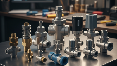
A combination valve brings several control functions into one compact body. In a hydronic heating circuit, it may isolate flow, prevent backflow, regulate pressure, and remove trapped air. Exact functions vary by design. That label alone is not enough. Check the flow arrow, pressure range, temperature rating, and installation diagram before choosing. Small details matter. A valve with a 22 mm connection may still require a different flow capacity.
Its main purpose is coordinated control. When a pump starts, the valve can help maintain stable pressure and protect circulation. During maintenance, an isolation function can reduce water loss and make servicing safer. In potable water systems, a combination valve may include shutoff, pressure reduction, and backflow protection. These features should match the system, not simply the available pipe size. In field inspections, a common mistake is assuming every combination valve performs every function.
Measure twice. Choose once.
Confirm the required flow rate, working pressure, fluid temperature, and connection type. Also consider access for cleaning or replacement. A valve can fit perfectly and still control poorly if pressure loss is ignored. I would also verify compatibility with seals, pipe materials, and local installation requirements. This step is easy to overlook, especially when the original valve has no clear markings. A careful selection may take longer, but it usually prevents noisy pipes, unstable pressure, and repeated adjustments.
A combination valve typically combines air-release, air-vacuum, and pressure-relief functions in one assembly. The chart below shows the theoretical water flow at a design velocity of 1.5 m/s for common pipeline internal diameters. Use the pipeline flow requirement, operating pressure, air volume, and surge conditions to confirm the correct valve size.
Flow values are calculated using Q = A × v, where Q is flow rate, A is pipe cross-sectional area, and v is water velocity. Actual combination-valve selection must also consider pipe diameter, maximum and minimum pressure, air-release capacity, vacuum protection, fluid type, and applicable design standards.
How to Choose the Right Combination Valve?
Identifying Your System’s Flow and Pressure Requirements
Choosing a combination valve starts with measured system conditions, not only the pipe diameter. Record the required flow rate during normal operation. Then check the minimum and maximum flow expected during start-up, shutdown, and seasonal changes. A valve sized for average flow may perform poorly at either extreme. It may also create unwanted noise.
Pressure requires equal attention. Measure the inlet and outlet pressure near the planned valve location. Calculate the available differential pressure under real operating conditions. Include pump variation, elevation changes, clogged filters, and pressure surges. A pressure gauge can reveal problems that a design drawing hides. Keep records from several operating cycles.
A useful approach is comparing the valve’s rated flow coefficient with the required flow and pressure drop. The selected valve should control steadily without remaining almost closed or fully open. Check fluid temperature, direction of flow, connection size, and maintenance access. During commissioning, adjust the valve gradually and confirm readings downstream. A quick estimate is tempting, but it can mislead. The first calculation is rarely perfect. Recheck it after the system reaches normal temperature and demand. Small errors in pressure assumptions can cause unstable control, poor circulation, or unnecessary pump energy use.
| Selection Dimension | Required Input or Typical Data | Engineering Method | Example or Reference Value | Selection Guidance |
|---|---|---|---|---|
| System Application | Heating, cooling, air-handling unit, fan-coil unit, radiant circuit, or terminal unit | Define whether the valve provides control, automatic flow limitation, isolation, measurement, or a combination of these functions. | Variable-flow chilled-water terminal unit | Use a combination valve when several functions are required in a compact assembly and the system benefits from stable flow control. |
| Design Heat or Cooling Load | Required thermal capacity of the coil or terminal unit | Q = P ÷ (1.163 × ΔT) | 100 kW load, 6 K water temperature difference: Q ≈ 14.3 m³/h | Use the design load and design temperature difference rather than the nominal capacity printed on the equipment. |
| Design Water Flow | Required flow rate through the controlled branch | Calculate from the load, fluid properties, and design temperature difference. Confirm the result against the equipment schedule. | Typical small terminal unit: 0.05–2.0 m³/h Typical larger coil branch: 2.0–20 m³/h |
Select a valve whose controllable flow range includes both the minimum operating flow and the design maximum flow. |
| Fluid Type | Water, water-glycol mixture, or another approved fluid | Check density, viscosity, temperature, concentration, and material compatibility. | Water-glycol mixtures have higher viscosity than water and may require additional pump head. | Use the actual fluid properties at operating temperature when calculating pressure drop and valve capacity. |
| Valve Capacity, Kv | Flow coefficient required for the selected valve | Kv = Q × √(SG ÷ ΔP) | For 5 m³/h of water at 0.25 bar valve pressure drop: Kv ≈ 10.0 | Choose a rated Kv that meets the design flow without forcing the valve to operate almost fully open under normal conditions. |
| Valve Capacity, Cv | Imperial flow coefficient where applicable | Cv = Q(gpm) ÷ √(ΔP(psi) ÷ SG) | For water, 100 gpm at 4 psi pressure drop: Cv ≈ 50 | Do not mix Kv and Cv values. Kv is commonly expressed with m³/h and bar; Cv is commonly expressed with US gpm and psi. |
| Available Differential Pressure | Pressure available across the valve at design flow | Determine the pump or system differential pressure after accounting for pipe, coil, fittings, and other valve losses. | Common control-valve design allowance: approximately 10–30 kPa, subject to the system design | A valve pressure drop that is too low can reduce authority and control stability; an excessive drop can waste pump energy. |
| Valve Authority | Ratio between valve pressure drop and total circuit pressure drop | a = ΔPvalve ÷ (ΔPvalve + ΔPcircuit) | 50 kPa valve drop and 50 kPa circuit drop: a = 0.50 | A higher authority generally improves controllability. The final value must be checked against the control strategy and pump operating range. |
| Maximum Working Pressure | Highest static and dynamic pressure expected in the piping system | Include pump shut-off pressure, fill pressure, thermal expansion, and pressure transients. | Example design requirement: valve rating at least 10 bar, where the system maximum is 8 bar | The valve pressure rating must be equal to or greater than the system design pressure at the applicable temperature. |
| Maximum and Minimum Temperature | Fluid temperature range and ambient temperature around the actuator | Compare the operating range with the valve body, seal, actuator, and insulation requirements. | Chilled-water service may operate near 6–12°C; heating-water service may operate near 60–90°C. | Allow for low-temperature condensation protection and verify that seals and actuator components are suitable for the full range. |
| Connection Size | Pipe connection type and nominal pipe size | Size the valve from required flow, allowable velocity, connection standard, and available installation space. | DN20, DN25, DN32, and DN40 are common sizes for many building-services terminal branches. | Do not select a valve only by matching the pipe diameter. A correctly sized valve may have a different internal flow passage. |
| Flow Velocity | Water velocity through the valve and adjacent pipework | Check velocity against noise, erosion, cavitation, and system design limits. | Many building hydronic systems use approximately 0.6–2.0 m/s in branch pipework, depending on design criteria. | High velocity can increase noise and pressure loss; very low velocity can make control resolution and air management more difficult. |
| Minimum Controllable Flow | Lowest stable flow required during partial-load operation | Compare the actuator rangeability and valve minimum controllable flow with the terminal unit’s turndown requirement. | Required operating range: 0.20–2.00 m³/h; desired turndown ratio: approximately 10:1 | Ensure the valve can regulate the minimum flow without hunting, excessive leakage, or loss of measurement accuracy. |
| Maximum Flow Limitation | Highest permitted design flow through the coil or branch | Set the automatic flow limiter or balancing function to the equipment design flow. | Design flow: 1.20 m³/h; maximum permitted flow setting: 1.20 m³/h | Automatic limitation can prevent excess flow in low-resistance branches and help maintain design distribution at varying system loads. |
| Control Signal | Command signal from the building automation or room controller | Verify actuator input, fail position, stroke time, feedback, and power supply. | Common signals include 0–10 V, 2–10 V, floating point, and three-point control. | The actuator signal and valve stroke direction must match the controller sequence for heating or cooling operation. |
| Shut-Off Requirement | Required tightness when the valve is commanded closed | Check the applicable leakage class, seat design, actuator closing force, and differential pressure at shut-off. | Cooling coils may require tight shut-off to prevent unwanted heat transfer during off cycles. | Use the specified leakage performance for the application; control accuracy and shut-off tightness are separate requirements. |
| Cavitation and Noise Check | Pressure drop, inlet pressure, outlet pressure, temperature, and fluid vapor pressure | Review the manufacturer’s cavitation limits and noise data using actual operating conditions. | Risk increases when pressure drop is high and downstream pressure approaches the fluid vapor pressure. | If risk is identified, reduce pressure drop, select a suitable trim, divide the pressure reduction, or revise the system arrangement. |
| Commissioning and Verification | Measured flow, differential pressure, actuator response, and control stability | Confirm the installed valve setting and compare measured values with the design schedule. | Verify design flow within the project’s specified tolerance, commonly around ±10% where applicable. | Record final settings and measured data so future maintenance and system balancing can be performed consistently. |
How to Choose the Right Combination Valve?
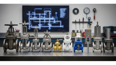
Choosing a combination valve starts with the fluid, pressure, temperature, and required flow control. A valve that works well in clean water may perform poorly with abrasive slurry or chemical media. Ball valves offer quick shutoff, while globe valves provide finer throttling. Check functions can prevent reverse flow. Some combination valves also include balancing or pressure-regulating features. More functions can save space, but they may complicate maintenance.
Material selection deserves careful attention. Stainless steel resists many corrosive fluids and frequent cleaning. Brass suits common water systems, but it may not fit every chemical application. Ductile iron handles demanding pipe sizes and moderate pressure efficiently. Always verify compatibility with seals, seats, and internal springs. The body material alone does not tell the whole story. I once focused too heavily on the valve body and overlooked seal temperature limits.
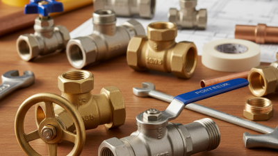
Connection options affect installation time and future repairs. Threaded ends suit smaller pipes and compact equipment. Flanged connections support larger systems and allow easier component replacement. Grooved connections can reduce installation labor, especially where space is limited. Press-fit connections look convenient, but they require compatible tools and accurate pipe preparation. Consider vibration, access, insulation, and local standards before ordering. A technical datasheet should confirm pressure ratings, flow coefficients, temperature limits, and testing methods. Small details matter.
Choosing a combination valve starts with compatibility, not appearance. Confirm the fluid, operating pressure, temperature range, flow rate, and connection size. Check the valve’s flow direction against the pipe layout. A valve that fits physically may still perform poorly in the wrong system. Review technical data, installation instructions, and certification details from reliable sources. When uncertainty remains, ask a qualified technician to verify the selection.
Safety features deserve close attention. Depending on the application, look for pressure relief, temperature control, backflow prevention, isolation, or drain functions. Make sure each feature matches the system’s actual risks. A relief mechanism should discharge safely, not toward electrical equipment or walkways. Some valves include strainers or inspection points, which can protect sensitive components and simplify testing. Small details matter.
Maintenance needs are easy to overlook. Choose a location with enough space for inspection, adjustment, and replacement. Check whether seals, cartridges, or strainers can be serviced without removing nearby pipework. Record the installation date and inspect for corrosion, leaks, unusual noise, or unstable temperature. I once underestimated access space, and a simple service task became unnecessarily difficult. That mistake changed how I review valve layouts. The best choice is not always the most complex one. It is the valve that remains safe, compatible, and serviceable over time.
Selecting a combination valve requires more than matching the connection size. Choose it from measured design flow, differential pressure, fluid temperature, and actuator authority. Do not size it by pipe diameter alone. That shortcut can produce noisy operation, unstable room temperatures, and unnecessary pump energy. ASHRAE Handbook guidance emphasizes verified flow, pressure control, and maintainable system design.
Long-term value depends on the valve’s complete service life. Check material compatibility, seal durability, corrosion resistance, and access for cleaning or replacement. A readable position indicator helps technicians diagnose faults beside a hot mechanical-room pipe.
The U.S. Department of Energy’s Building Energy Data Book reports that HVAC systems can represent about 40% of commercial building energy use. Small control errors can therefore become expensive over time. The cheapest valve may not be the lowest-cost choice.
The 2023 Global Status Report for Buildings and Construction states that buildings consumed about 34% of global energy demand in 2022. Efficient hydronic control deserves careful attention. Specify a valve with a documented flow coefficient, tested shutoff performance, and clear maintenance requirements. Review pressure-drop data at actual operating conditions. A spreadsheet can miss dirt, poor commissioning, or oversized pumps. That is the uncomfortable part. Selection is never perfect. A modest design margin, regular inspection, and recorded commissioning data usually protect performance better than optimistic assumptions.